Power Relay Station
| Power Relay Station |
|---|

|
The power relay station is the junction box for all systems of the spacecraft. The power relay station enables ad hoc repairs to damaged systems. Power distribution can be configured to reroute power from working systems to systems that are not working. Less important systems can be sacrificed in favor of systems necessary for survival of the ship and crew. Using the power relay station, a skilled engineer can revive an otherwise derelict ship so it can limp back to port for repairs.
Improper use of the power relay station can result in catastrophic system failure and total destruction of the spacecraft.

Controls are activated by clicking on the console using the hand cursor. Controls also have corresponding keyboard equivalents. Help about using the hand cursor and a table showing the key commands for this station can be found on the Controls#Power_Relay_Station page.
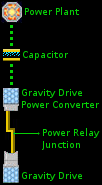
Power Relay Schematic

- The power plant converts hydrogen fuel into electrical energy. Electricity produced by the power plant is stored in the capacitor. Each power plant unit adds to the total energy storage capacity of the capacitor.
- The capacitor acts as a ready supply of electrical energy for the systems of the spacecraft. Unlike a battery, which releases energy slowly, the capacitor responds instantly to large sudden demands for power. The amount of energy that can be stored by the capacitor is determined by the number of power plant units in the design.
- Each system has a power converter. The power converter directs power from the capacitor to the system equipment through a power relay junction. The power converter for each system is designed to handle the energy load demanded by its system. The maneuver drive power converter often routes a lot of power because a large number of maneuver drive units is typical in a spacecraft design.
- A power relay junction connects a power converter to system equipment. Normally, every power converter has one single power relay junction connecting to its corresponding system equipment. The figure depicts the maneuver drive power converter connected to the maneuver drive equipment, which is the normal state.
- System equipment is the final consumer of the electrical power produced by the power plant. System equipment performs the specific function of the system. The maneuver drive provides propulsion through space and creates an artificial maneuver environment inside the spacecraft.
Condition Red

When a system is damaged, the damage affects the power converter for the system, not the equipment of the system.
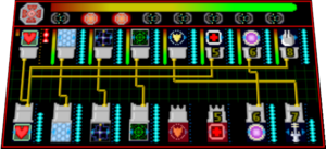
This is crucial to understanding the role of the power relay station. Damage to a system reduces the output of that system's power converter. The full potential of the system equipment can be restored by connecting other working power converters to the system's equipment. Using the power relay station, multiple power converters can be connected to the equipment of a single system.

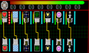
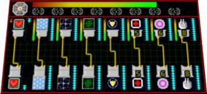
The display screen is divided into two sections by red lines. The small upper section displays the power plant shunts. The large lower section displays the power relay junctions.
Power Relay Junctions
The power relay junction section displays power converters in a row across the top. System equipment is displayed in a row across the bottom. Power junctions are displayed as thick gold traces connecting power converters at the top to system equipment at the bottom.


Access to every system's power relay junction is possible, even though only eight junctions can be displayed at once.
The power converter displayed at any position is changed by clicking on the blue arrows on the system type image. Click on the right arrow to switch to the next system's power converter in the ship's internal list of systems. Click on the left arrow to switch to the previous system's power converter. In this manner, each power converter position on the panel can be "scrolled" to show a different power converter among those available.
The system equipment displayed at any position is changed by clicking on the blue arrows on the system type image. Click on the right arrow to switch to the next system's equipment in the ship's internal list of systems. Click on the left arrow to switch to the previous system's equipment. In this manner, each system equipment position on the panel can be "scrolled" to show a different system among those available.
Note that the power converters shown at the top row do not have to correspond to the system equipment shown at the bottom row.
When one end of a power relay junction is not visible on the display, the gold junction line is drawn from the visible end to one side of the display screen.
Making Connections
Click on the connector at the power converter end of a gold junction line to disconnect the system. Power converters are shown across the top of the power relay section.
The last power converter that is clicked becomes the current converter when making a junction to the next equipment connection that is clicked.
Click on the connector above a system equipment image to create a junction to the last converter that was clicked. System equipment is shown across the bottom of the power relay section.
Smaller power converters may not supply all of the power needed by equipment of larger systems. Multiple power converters can be connected to the same system equipment.
Overclocking
Overclocking is a way of restoring lost performance to a damaged system. The degraded performance level of a damaged system can be doubled by overclocking, up to its undamaged design performance. A system cannot be overclocked beyond its original designed performance.
Click on the power level bar next to a power converter to overclock it, resulting in a possible increase in performance of that system.


WARNING!
Overclocked systems will incur damage due to stress over time. This can result in catastrophic system failure and total destruction of the spacecraft.Power Plant Shunts
The upper section of the power relay station displays power plant output and power plant shunts.

Power plant shunts appear in a row across the bottom. Eight different shunts enable risky overrides inside the power plant. Each shunt that is activated restores 1/8th of the power plant's undamaged output. Shunts will restore power plant output lost due to damage, up to 100%; they will not enable the power plant to exceed its original design capability.

WARNING!
Active shunts will damage the power plant over time. This can result in catastrophic failure of the power plant and total destruction of the spacecraft.The output of the power plant is shown as a horizontal bar across the top. When no shunts are enabled, this bar corresponds to the power plant damage percentage shown on the Damage Report (F6) window. Active shunts will raise the output of the power plant beyond the health level of the power plant.


