Design Parts
Designs are made up of parts. Here is a comprehensive list of all of the parts that can comprise a design.
Some parts are only available depending on if it is a building design, spacecraft design, or other.
Barrier

Barriers created obstructions to movement and gunfire inside voids.
Barriers are not visible when the design is seen in the game environment.
Barriers create floors for things on top of them. Use barriers to create the floors of ramps and stairs. When creating stairs, it is much more efficient to make a ramp-floor under the steps than to create complex or many barriers to simulate every step.
Barriers can be associated with a state of a door or landing gear. This determines which barriers are obstructions when the door or landing gear is operated. It is ok to associate more than one barrier with a state of a door or landing gear.
Berth, Capt

Capt berth is the place where the captain sleeps. Only a human player can occupy the capt berth.
A design can have only one capt berth. Attempting to add additional capt berths causes the existing capt berth to move to the new location, instead of adding a new one.
The cursor depicts a space that is 1m x 2m.
An avatar enters their berth by pressing the E key. While in their berth, an avatar can access their personal sea chest.
Berths are only placed in spacecraft designs. Berths are not used in building designs.
Berth, Crew

Berth, Officer

Berth, Passenger

Berth, Troop

Build Zone

Camera

Console, Command

Console, Engineer

Console, Fire Control

Console, Helm

Console, Medic


Console, Power Relay

Console, Sensor

Console, Shield

Console, Transporter

Contrail Emitter

Decal

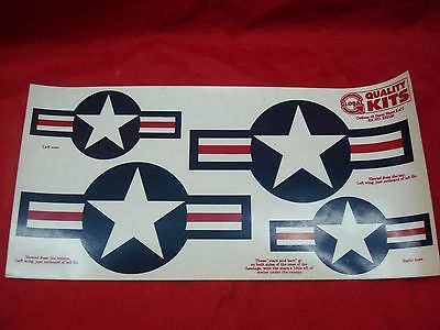
Decal parts are intended to simulate the decals applied to plastic models. They typically arrive on a sheet.

A decal's faces are textured like the faces of any other part. When rendered, faces of decals are blended onto the faces of underlying geometry. OpenGL is configured to enable decals to exist in the same plane as other surfaces, without getting culled or causing unwanted surface collisions.
Decals should generally be placed where they conform to an existing surface, though this is not strictly necessary if a desirable visual effect is achieved by using them otherwise.
Decal, Berth Name

A berth name decal is a rectangle for displaying the name of the person assigned to a berth. When the associated berth is not assigned, the berth name decal shows Unassigned.
The name decal is created by entering two corner points of a rectangle. The name decal is oriented to the grid, with +X going to the right and +Y going up on the name decal. After creating a berth name decal, it should be associated with a berth, to show the assignee's name.
Steps:
- A corner point of the name decal is entered.
- The opposite corner point of the name decal is entered.
Key Commands:
Crestarts the action at the beginning.
Decal, Capt Name

A name decal is a rectangle for displaying the name of the captain of the spacecraft.
The name decal is created by entering two corner points of a rectangle. The name decal is oriented to the grid, with +X going to the right and +Y going up on the name decal.
Steps:
- A corner point of the name decal is entered.
- The opposite corner point of the name decal is entered.
Key Commands:
Crestarts the action at the beginning.
Decal, Empire Flag

A flag decal is a rectangle for displaying the flag of the empire.
The flag is created by entering two corner points of a rectangle. The flag is oriented to the grid, with +X going to the right and +Y going up on the flag.
The flag rectangle should be square or nearly square in aspect ratio. It should have faces behind it. The flag that gets displayed in the area may not be square in shape. The flag's aspect ratio will be preserved, exposing faces behind the flag, or visible through holes in the flag.
Steps:
- A corner point of the flag is entered.
- The opposite corner point of the flag is entered.
Key Commands:
Crestarts the action at the beginning.
Decal, Empire Name

A name decal is a rectangle for displaying the name of the empire.
The name decal is created by entering two corner points of a rectangle. The name decal is oriented to the grid, with +X going to the right and +Y going up on the name decal.
Steps:
- A corner point of the name decal is entered.
- The opposite corner point of the name decal is entered.
Key Commands:
Crestarts the action at the beginning.
Decal, Ship Name

A name decal is a rectangle for displaying the name of the spacecraft.
The name decal is created by entering two corner points of a rectangle. The name decal is oriented to the grid, with +X going to the right and +Y going up on the name decal.
Steps:
- A corner point of the name decal is entered.
- The opposite corner point of the name decal is entered.
Key Commands:
Crestarts the action at the beginning.
Door

Doors are used to interconnect rooms and to connect the rooms inside a design with the outside.
Doors open and close in response to players and NPCs. Each door can provide geometry for its appearance when open, closed, and several states in between for animation. The open state often has no geometry, which is typical, though it could have geometry, such as a door swung open. The closed state is usually drawn to look like it would block your way; otherwise it is confusing to players when they cannot move through the closed doorway. The geometry of each door state has no effect on obstructions; it just looks nice.
Doors have two door switches. The default location for door switches is the center of the door geometry. Door switches can be moved anywhere else in the design. They are not visible. The architect must create some geometry to give a visual cue of its presence, if desired.
Doors can be locked, to restrict who is allowed to open them. Each door can provide geometry for its appearance when locked and unlocked. When no locked states are provided, the unlocked door states are used.
Doors can be stuck in the open or closed state. Each door can provide geometry for its appearance when stuck open and stuck closed. When no stuck states are provided, the normal door states are used.
The open state of a door is associated with one or more voids. Those voids are only accessible when the door is in the open state. That is what makes doors work to permit movement from one room void to another or from a room void to outside.
The open state of a door is associated with one or more walk paths or ladder paths. This allows NPCs to find a path through the door, and to know it needs to be opened first.
Interior Door Structure

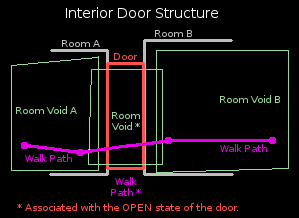
The Interior Door Structure diagram shows how an interior door should be constructed in the design.
The architect designs two rooms where a door is needed. Room voids are added to each room; they do not overlap, which prevents people from moving from one room to the other room.
A door hole is cut into each opposing room wall. The shape of the door opening is arbitrary. The walls to be connected are parallel in the diagram but that is not a requirement. The sides of the opening are lined with faces to make a seamless passage between the rooms. A door part is created to fill the hole, appearing to block the opening.
Door jigs exist to make this connection automatically. They cut the walls, line the passage way, and create a basic door.
A room void is created that intersects both room voids through the doorway, creating a connection between them that a person can move through. That room void is associated with the open state of the door. Then the room void is only there and passable when the door is open.
That is enough for human players to use the door. However, Hazeron is populated by dumb NPCs that need a little help.
Walk paths are added for NPCs. Walk paths should be added to connect each room. The walk path through the door is usually a single segment that starts and ends in the room voids on each side of the door. The ends should place an NPC close enough to the door switch to operate the door. The ends must be inside room voids that are not associated with the door, so they can be reached when the door is open or closed. The walk path through the door is also associated with the open state of the door.
The walk path through the door should be connected with the rest of the path network on each side of the door, if any.
Hull Door Structure

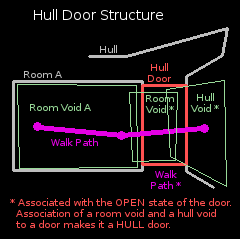
The Hull Door Structure diagram shows how an exterior door should be constructed in the design.
The architect designs a hull and places a room inside where an exterior door is wanted.
A room void is added to the room. There is no connection between the inside and the outside of the design.
A door opening is cut through to the outside and a door part is created to block the opening. Use a jig.
A room void is added that intersects Room Void A and ends somewhere inside the door. The person going through the door is "inside" the ship while inside this room void, or any room void.
A hull void is added that intersects the room void inside the door and extends out through the door.
The hull void and the door room void are associated with the open state of the door. The association of both a room void and a hull void to a door is what distinguishes the door as a hull door. Then the room void and the hull void are only there and passable when the door is open.
Walk paths are added for NPCs. Walk paths should be added to connect the room void to the outside. The walk path through the door is usually a single segment from the interior room void to outside the door. The ends should place an NPC close enough to the door switch to operate the door. One end must be inside the interior room void, so NPCs can move there when the door is closed. The other end of the walk path must be accessible from the outside when the door is closed or open. The walk path through the door is also associated with the open state of the door.
In the interior room void, the walk path through the door should be connected with the rest of the path network.
Due to the obstruction model, it may also be necessary to add another hull void just outside the door (not pictured). Do not associate it with the door. That hull void may be needed to allow people to move close enough to the door to operate the door switch.
Fence

Game Table

Hull

Jig, Cutting

Jig, Decal

Jig, Door

A door jig can be used to make a door between an interior room and the outside of the hull. A door jig can also be used to make a door between two interior rooms.
Jig, Launch Tube

Jig, Window

A window jig can be used to make a window between an interior room and the outside of the hull. A window jig can also be used to make a window between two interior rooms.
Landing Gear

Light Bulb

Light Lens

Mesh


Panel, Capacitor

Panel, FTL Drive

Panel, Life Support

Panel, Maneuver Drive

Panel, Power Plant

Panel, Sensor

Panel, Shield

Panel, Weapon

Parking Spot, Ground Vehicle

Parking Spot, Spacecraft

Parking Spot, Space Rocket

Parking Spot, Space Vehicle

Parking Spot, Water Vehicle

Path, Ladder

Path, Walk

Pod Bay

Post, Citizen

Post, Livestock

Post, Troop

Room

Rotating Beacon Lens

Shrub

Site

Sketch

Space Vehicle Landing System

Space Vehicle Launcher

Station, Command

Station, Designer

Station, Engineer

Station, Fire Control

Station, Helm

Station, Medic


Station, Power Relay

Station, Sensor

Station, Shield

Station, Transporter

Status, Alert

Status, Life Support

Status, Mission

Status, World Map

Strobe Lens

Tree

Turbo Lift

Turbo lifts work like elevators. They move from one stop to another, at the request of the passengers. Unlike a real elevator, a turbo lift teleports instantly to each stop.
This enables separate interior sections of a design to be connected in a way that feels contiguous to players. Turbo lifts also enable separate sections to be interconnected when the geometry to create the passage ways between them might be difficult or impossible to make.
Turret

Void, Environment

Void, Room

Room voids exclude or erase portions of the obstruction model. Objects inside a room void are never considered to be blocked by the hull obstruction model, though they may be blocked by barriers.
Room voids are not visible in the game environment. Room voids allow the visible room geometry to be complex while keeping the room void simple. Simplicity is critical for room voids, to minimize the CPU's work when using them in calculations.
Room voids provide a habitable environment. Objects inside a room void are considered to be inside the design.
Room void lights can be turned on and off.
Room voids offer a choice of internal gravity options.
Room voids enable access to the cargo hold.
Options for room void gravity and hold access are configured when the void is created. Room void properties can be changed afterwards using Part, Properties, Room Void Gravity and Hold Access.
Room voids are usually grouped with the visible room geometry of the room. That way, the room geometry is lit according to the lights in the room void. The name of the group is the name of the room that will be seen in the game.
Room voids may be associated with a state of a part. Doors associate a room void with their open state, to create a passage that is only accessible when the door is opened.
Void, Hull

Hull voids exclude or erase portions of the obstruction model. Objects inside a hull void are never considered to be blocked by the hull obstruction model, though they may be blocked by barriers.
Depressions and cavities formed in a single hull part may result in unwanted obstructions. For example, a thruster nozzle made from a single conical hull part would be obstructed inside the cone; a hull void could be used to permit movement into the cone.
Gravity inside hull voids matches the environment around the spacecraft or building.
Hull voids are also integral to describing a hull door. Refer to the section on doors.
- Faces of a void must form an airtight shell.
- Faces of a void must be flat, not bent. Use triangles to make bumpy voids. Do not bend quads or poly faces.
- Use voids sparingly and strictly limit the number of faces. Overall size of a void is not a factor; number of faces is the critical resource that must be minimized.
- Multiple voids with few faces is strongly preferred over elaborate voids with many faces. It is far better to intersect two long boxes than to make a single cross shaped void.
- Voids may overlap other voids, allowing movement from one void to the next. A small amount of overlap is more reliable than trying to abut them perfectly and it's easier to draw.
- Hull voids should extend outside the obstruction model so there is no ambiguity when entering or exiting. Excess hull void that extends beyond the obstruction model has no negative consequence.
Window

Window parts exist primarily to create windows between the inside and outside of a building or spacecraft. However, windows can also be used to join rooms and they can be used for decoration.
A transparency value is assigned to windows. Transparency may be set to invisible. Invisible windows are not useful for any purpose.
Windows glow in response to internal lighting conditions. Transparent windows should be grouped with the room that contains them, to be lit appropriately.
Transparency may be set to translucent. Translucent windows are decorative, glowing in response to simulated internal lighting conditions. This makes them useful to create a facade, suggesting interior rooms where none exist, by creating the appearance of many windows.
Translucent decorative windows may be grouped to cause them to be lit the same, as if they are all part of the same room.
Avoid situations where the player may see through several windows at the same time. This will often produce undesirable results.