Designer: Difference between revisions
(→The menu buttons: Added the pictures Haxus added.) |
|||
| Line 30: | Line 30: | ||
==Designer Interface== | ==Designer Interface== | ||
The designer interface is dominated by a first person 3D view of the design space. It is in this space that the design will be created. | |||
Hover the mouse pointer over most buttons and controls to see a tool tip. Tool tips on buttons explain their function and they sometimes reveal features that are not obvious at first. The tool tips on some buttons change, depending on current conditions. | |||
===Menu Bar=== | |||
[[file:DesignerMenu.png|right|Menu Bar]] | |||
At the top of the designer interface is a menu bar. Most functions of the program can be accessed using the menu bar. | |||
===Input Tool Bar=== | |||
[[file:DesignerInputBar.png|right|Input Tool Bar]] | |||
The ''Input Tool Bar'' appears below the menu bar, at the left. It can be moved by dragging the dotted grip at the left end. Tool tips on the buttons explain their function. | |||
===Reference Tool Bar=== | |||
[[file:DesignerReferenceBar.png|right|Reference Tool Bar]] | |||
The ''Reference Tool Bar'' appears below the menu bar, to the right of the input tool bar. It can be moved by dragging the dotted grip at the left end. | |||
===Parts=== | |||
[[file:DesignerParts.png|right|Parts]] | |||
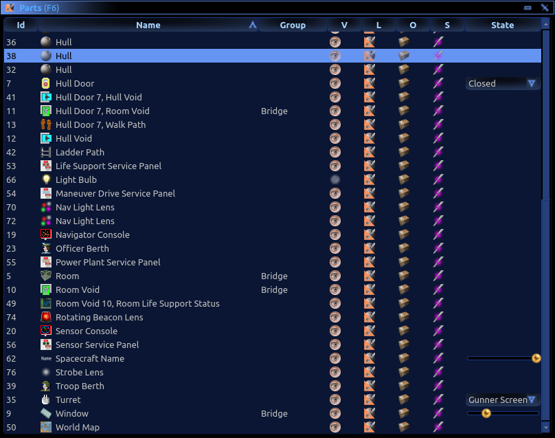
The ''Parts'' window is displayed using the F6 key or the menu. It is typically docked at the right side of the designer window. | |||
The parts list contains every [[Design_Parts|part]] that is in the current design. This includes hull objects, imported meshes, rooms, berths, etc. This allows you to easily see everything within the design at once, and also provides buttons for toggling the visibility of each part, as well as other part properties. | |||
The Parts list is also useful for selecting parts and deleting parts. | |||
====Id Column==== | |||
Every part in a design is assigned a unique id number. Part id numbers may range from 1 to 65,535. | |||
Part id numbers are not preserved when copied and pasted between designs. Parts are assigned new ids when pasted into a design. | |||
====Name Column==== | |||
The name column starts with an icon that indicates the kind of the [[Design_Parts|part]]. | |||
The icon is followed by a text name assigned to the part. Names are assigned by the designer based on the type and properties of the part. | |||
====Group Column==== | |||
The group column shows the name of the group assigned to each part. | |||
Select one or more parts and right-click to assign them to a group. Group names are chosen by the architect. Parts are assigned to groups as needed. | |||
Groups organize parts together. | |||
In building and spacecraft blueprints, groups define the rooms. | |||
In fence designs, two specific groups are required: ''Post'' and ''Section''. | |||
===='''V'''isibility Column==== | |||
Shows and controls the visibility state of parts. | |||
Parts can be made invisible to simplify the design view. Invisible parts are not selected when using the mouse in the scene. Editing functions do not operate on invisible parts. | |||
Left click to toggle the visibility of the selected parts. Right-click to choose visibility from a menu. | |||
Making a part invisible does not exclude it from the final design. Invisible parts are included in the final design. | |||
===='''L'''ock Column==== | |||
Shows and controls the locked state of parts. | |||
Lock parts to protect them from accidental editing. The locked state of parts has no effect in the final design. | |||
Left click to toggle the lock of the selected parts. Right-click to choose the locked or unlocked state from a menu. | |||
===='''O'''mit Column==== | |||
Shows and controls whether a part is omitted from the final design. | |||
Omit parts to prevent them from being included in the final design. Omitted parts are excluded from the design analysis report. Some parts are always omitted; they cannot be included. | |||
Excluded parts can be useful for reference purposes, as a way to keep images or geometry in the design that are not intended to be part of the final design. Parts that exist only as design tools are omitted regardless of this setting, e.g. door jigs. | |||
===='''S'''eal Column==== | |||
Shows and controls whether a part is sealed. | |||
Parts remember who their architect was. Seal parts to prevent other architects from editing them in face mode. '''Only the architect of a part can seal or unseal the part.''' | |||
Sealed parts can be used in part mode like other whole parts. They can be moved, stretched, rotated, copied to the clipboard and saved into files. Whole part editing operations are mostly disabled when a sealed part is selected, to protect the design of the part from changes. | |||
A sealed part can be used as a jig but it cannot be cut using a jig. | |||
Only the architect of a sealed part can enter face mode when the part is selected. This prevents individual faces of sealed parts from being modified or copied to the clipboard by other architects. | |||
The design report lists all architects whose parts are included in a design. | |||
====State Column==== | |||
{| class="wikitable" | {| class="wikitable" | ||
| Line 54: | Line 122: | ||
| style="text-align:center;" | [[file:ScShow.png|40px]] | | style="text-align:center;" | [[file:ScShow.png|40px]] | ||
| style="text-align:center;" | [[file:ScHide.png|40px]] | | style="text-align:center;" | [[file:ScHide.png|40px]] | ||
| Toggles | | Toggles whether or not the part is visible. | ||
|- | |- | ||
! Lock Toggle | ! Lock Toggle | ||
| style="text-align:center;" | [[file:ScLock.png|40px]] | | style="text-align:center;" | [[file:ScLock.png|40px]] | ||
| style="text-align:center;" | [[file:ScUnlock.png|40px]] | | style="text-align:center;" | [[file:ScUnlock.png|40px]] | ||
| | | Toggles whether or not the part can be modified. | ||
|- | |- | ||
! Omit Toggle | ! Omit Toggle | ||
| style="text-align:center;" | [[file:ScOmit.png|40px]] | | style="text-align:center;" | [[file:ScOmit.png|40px]] | ||
| style="text-align:center;" | [[file:ScInclude.png|40px]] | | style="text-align:center;" | [[file:ScInclude.png|40px]] | ||
| | | Toggles whether or not the part is included in the final design. | ||
|- | |- | ||
! Seal Toggle | ! Seal Toggle | ||
| style="text-align:center;" | [[file:ScSeal.png|40px]] | | style="text-align:center;" | [[file:ScSeal.png|40px]] | ||
| style="text-align:center;" | [[file:ScUnseal.png|40px]] | | style="text-align:center;" | [[file:ScUnseal.png|40px]] | ||
| | | Toggles whether or not the part is sealed. | ||
|} | |} | ||
===Texture Wrapper=== | |||
[[file:DesignerTextureWrapper.png|right|Texture Wrapper]] | |||
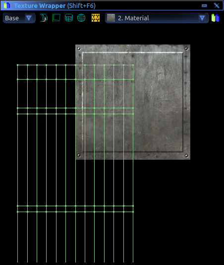
The ''Texture Wrapper'' window is displayed using the Shift+F6 key or the menu. It can be docked stacked on top of the parts window; tabs will appear at the bottom, to choose between them. | |||
Once inside a studio, display the ''Design'' (F6) window. Nearly every function and button has a usage tip that appears once clicked which describes what the function does. Use the exit button to return to the game environment. | |||
[[file:NewDesignerInterface.png|400px|thumb|right|An image of the new designer interface.]] | |||
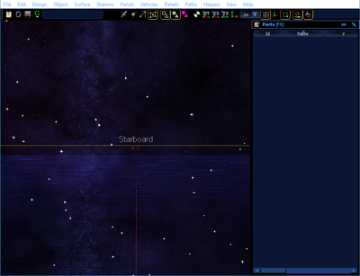
The new designer interface is accessible through both the offline launcher and in-game while online. Upon entering, you are inside a bounding box (yellow lines) that define the design area, with a grid underneath you that is split with two axis. | |||
The interface is heavily based on menus as seen at the top of the screenshot. This means there are a lot less buttons immediately visible. The F6 hotkey or the designer button on the left toggles both the Parts list on the right of the image and the black bar with all the buttons seen at the top of the screenshot. However, it does not toggle the white menu buttons seen at the top above the black bar. | |||
'''Note that the black bar is able to be moved by clicking the dots on the left edge of the bar, while the Parts list seen on the right can be docked and re-positioned normally.''' | |||
===The Parts list=== | |||
===The menu buttons=== | ===The menu buttons=== | ||
Revision as of 17:05, 13 July 2020
| This section is in need of revision. Please help improve it or discuss these issues on the talk page. The reason given is: The new designer (See Spacecraft Update and Building Update) is already functional. This page need more information about basic designer functions. Could use some help. |
The Designer is a modeling tool used to design spacecraft and building blueprints.
Blueprints
Spacecraft and buildings are described using blueprints. Blueprints contain all of the information needed to represent a building or spacecraft in the game, such as its 3D model and design specifications. Blueprints are stored in a universal library where they are accessed by spacecraft and buildings during game play.
Blueprints can be saved onto media items in an avatar's gear. Blank paper and blank disks can each hold only one blueprint. Storage devices can hold varying numbers of blueprints, depending on the device.
The blueprint exchange provides a place for players to share blueprints. Separate exchanges for spacecraft blueprints and building blueprints are accessed in the game. At the exchanges, blueprints can be published by designers and they can be purchased by other players, using in-game cronodollars, not real money.
Publishing is a way to share blueprints with other players. A blueprint does not have to be published to be used in the game. A blueprint only needs to be saved onto a storage device in your gear to be used to make buildings or spacecraft.
Spacecraft, buildings, and storage devices reference their blueprints in the library throughout their lifetimes. Blueprints that are in use by game objects cannot be deleted. When a player deletes a blueprint, it may instead be deactivated in the library, until it is no longer referenced and it can be finally removed.
Designer Access
The designer can be accessed both online and when playing offline solo.
Online Designer
Online, a designer is accessed by going to a design studio building or by accessing a designer station while aboard a spacecraft.
To enter a designer at a design studio, display the Building (F10) window and click on the "Enter" button of a studio. When a studio is "Vacant", you may leave the password box blank or you may enter a password of your choice. The password you enter establishes that studio's password until the studio becomes vacant. To join an "Occupied" design studio, you must enter the password that was established by the first person to enter the studio.
To enter a designer aboard a spacecraft, move to a designer station and enter the station by pressing the E key. Designers aboard a spacecraft are not password protected. Each designer station creates its own designer instance. People who enter the same designer station are placed in the same designer instance. The avatar enters the designer instance and their body does not remain at the station in the ship, like it does with other stations.
Players may work together in the same studio to develop a design. In this case, the first player to enter the vacant studio is registered as the architect and owner of the design.
Offline Designer
When the game is launched, the designer can be entered solo, instead of logging in to the game. Overall program performance is better when designing solo because no server is involved. Once a design is completed solo, it can be saved to a .SoH file. That file can be loaded into the on line designer, for storage in the universal library.
Designer Interface
The designer interface is dominated by a first person 3D view of the design space. It is in this space that the design will be created.
Hover the mouse pointer over most buttons and controls to see a tool tip. Tool tips on buttons explain their function and they sometimes reveal features that are not obvious at first. The tool tips on some buttons change, depending on current conditions.
Menu Bar

At the top of the designer interface is a menu bar. Most functions of the program can be accessed using the menu bar.
Input Tool Bar

The Input Tool Bar appears below the menu bar, at the left. It can be moved by dragging the dotted grip at the left end. Tool tips on the buttons explain their function.
Reference Tool Bar

The Reference Tool Bar appears below the menu bar, to the right of the input tool bar. It can be moved by dragging the dotted grip at the left end.
Parts

The Parts window is displayed using the F6 key or the menu. It is typically docked at the right side of the designer window.
The parts list contains every part that is in the current design. This includes hull objects, imported meshes, rooms, berths, etc. This allows you to easily see everything within the design at once, and also provides buttons for toggling the visibility of each part, as well as other part properties.
The Parts list is also useful for selecting parts and deleting parts.
Id Column
Every part in a design is assigned a unique id number. Part id numbers may range from 1 to 65,535.
Part id numbers are not preserved when copied and pasted between designs. Parts are assigned new ids when pasted into a design.
Name Column
The name column starts with an icon that indicates the kind of the part.
The icon is followed by a text name assigned to the part. Names are assigned by the designer based on the type and properties of the part.
Group Column
The group column shows the name of the group assigned to each part.
Select one or more parts and right-click to assign them to a group. Group names are chosen by the architect. Parts are assigned to groups as needed.
Groups organize parts together.
In building and spacecraft blueprints, groups define the rooms.
In fence designs, two specific groups are required: Post and Section.
Visibility Column
Shows and controls the visibility state of parts.
Parts can be made invisible to simplify the design view. Invisible parts are not selected when using the mouse in the scene. Editing functions do not operate on invisible parts.
Left click to toggle the visibility of the selected parts. Right-click to choose visibility from a menu.
Making a part invisible does not exclude it from the final design. Invisible parts are included in the final design.
Lock Column
Shows and controls the locked state of parts.
Lock parts to protect them from accidental editing. The locked state of parts has no effect in the final design.
Left click to toggle the lock of the selected parts. Right-click to choose the locked or unlocked state from a menu.
Omit Column
Shows and controls whether a part is omitted from the final design.
Omit parts to prevent them from being included in the final design. Omitted parts are excluded from the design analysis report. Some parts are always omitted; they cannot be included.
Excluded parts can be useful for reference purposes, as a way to keep images or geometry in the design that are not intended to be part of the final design. Parts that exist only as design tools are omitted regardless of this setting, e.g. door jigs.
Seal Column
Shows and controls whether a part is sealed.
Parts remember who their architect was. Seal parts to prevent other architects from editing them in face mode. Only the architect of a part can seal or unseal the part.
Sealed parts can be used in part mode like other whole parts. They can be moved, stretched, rotated, copied to the clipboard and saved into files. Whole part editing operations are mostly disabled when a sealed part is selected, to protect the design of the part from changes.
A sealed part can be used as a jig but it cannot be cut using a jig.
Only the architect of a sealed part can enter face mode when the part is selected. This prevents individual faces of sealed parts from being modified or copied to the clipboard by other architects.
The design report lists all architects whose parts are included in a design.
State Column
Texture Wrapper

The Texture Wrapper window is displayed using the Shift+F6 key or the menu. It can be docked stacked on top of the parts window; tabs will appear at the bottom, to choose between them.
Once inside a studio, display the Design (F6) window. Nearly every function and button has a usage tip that appears once clicked which describes what the function does. Use the exit button to return to the game environment.

The new designer interface is accessible through both the offline launcher and in-game while online. Upon entering, you are inside a bounding box (yellow lines) that define the design area, with a grid underneath you that is split with two axis.
The interface is heavily based on menus as seen at the top of the screenshot. This means there are a lot less buttons immediately visible. The F6 hotkey or the designer button on the left toggles both the Parts list on the right of the image and the black bar with all the buttons seen at the top of the screenshot. However, it does not toggle the white menu buttons seen at the top above the black bar.
Note that the black bar is able to be moved by clicking the dots on the left edge of the bar, while the Parts list seen on the right can be docked and re-positioned normally.
The Parts list
This section describes what each of the menu buttons generally contain at the top of the interface. Note that all of the buttons under these by default give a usage tip on click.
| Menu Buttons |
|---|
|
The buttons on the black bar are also very useful. Note that hovering over any of these buttons gives a tooltip for usage.
| Black Bar buttons |
|---|
|
General Design Process
There are several steps to creating a ship that can be finalised. In general, from the in-designer Usage Tip, the order is like this;
- Create an exterior hull.
- Create one or more rooms inside the hull.
- Cut out doors and windows.
- Create finer model details.
- Apply textures and other effects to finish the surfaces.
- Add details: control stations, berths, lights, display screens, etc.
- Add room voids.
Design -> Finalise Design performs checks to ensure that the ship has valid paths, rooms, hulls, and that specific elements are reachable. This is what is used to prepare a spacecraft design for manufacturing. This will list errors such as no fuel, no capacitor, no doors, missing hull, etc.
Most equipment from the old designer has been removed, however, elements such as lighting and console stations remain. This equipment is found under "Vehicles", "Details", "Paths", alongside "Stations". This equipment mostly functions the same, and is still required for a functioning spacecraft. A table below shows what each unit does.
Jigs
Jigs are found underneath the Design Menu button. There are many different types of Jigs, such as Door Jigs, Window Jigs, Launch Tube Jigs, Cutting Jigs, and Decal Jigs. They are created like any other hull or room objects, by selecting the Shape type (Extrusion, Sphere, Tubing, Spindle) and drawing the shape wanted. A physical object is then created and added to the Parts list as a Jig of the type selected.
Jigs are used by positioning the created Jig object between two rooms, or between a hull and room, ensuring that the Jig penetrates both walls. Once this is positioned correctly, select all 3 objects at once using the Parts panel, and then select "Jig Cut" under the Design Menu button. The jig then cuts the walls in the shape of the jig, allowing you to create tube hallways as an example. The cut walls are then converted to the object type of the jig, such as the walls being converted into transparent glass if using a Window Jig, or door objects if using a Door Jig.
Jigs can be used in order to create different types of objects, exits or walls between two rooms or the interior and exterior of a design. For example, the Door Jig creates a door between whatever rooms the Jig is placed between. The Window Jig creates a Window between the rooms, while the Launch Tube and Cutting jigs just create holes between the hull and room and cut the faces of each side, respectively.
All jigs create faces between the two walls that they penetrate, in order to give walls thickness and prevent you from seeing any back-faces.
Editing existing models
If a quad or a face gets moved then it will distort the texture on it. For this reason triangles are preferred to be used if the model is going to be sculpted. When creating a triangle or quad, drawing it clockwise will have it face the camera. Building it counter clockwise will have it face away from the camera.
Vertices that are at the same spot will stick together. If you want to pull off a face or a triangle then select the edit face and move that. Always be ready to press Ctrl Z to undo things if things go wrong.
Walk Paths
In order for NPCs to successfully move around the interior of a design with multiple rooms. The walk paths need to be above the floor, hip height is usually good. The NPCs will need to be able to always have a clear line to the nearest walk path end, or else they will get stuck. Walk paths need to form a full network where each walk path has to start where another ends, so that an NPC that is standing in one room can go to their nearest walk path end and then path through the net work to their destination room.

Spacecraft Design
For spacecraft designer specific information, see the Spacecraft Design page.
Building Design
For building designer specific information, see the Building Design page.