Helm Station
| Helm Station |
|---|

|
The helm station controls the movement and attitude of the spacecraft. Controls for interior and exterior lighting and door locks are also found on the helm.
Controls are activated by clicking on the console using the hand cursor. Controls also have corresponding keyboard equivalents. Help about using the hand cursor and a table showing the key commands for this station can be found on the Controls#Helm page.
Console

Upper Portion
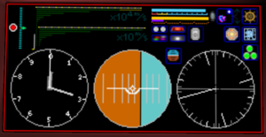
The kill button is a large red button at the top left. Press the kill button to set the throttle to neutral.
The throttle appears as a vertical line of blue dots next to the kill button. The throttle can be adjusted forward or backward to direct engine thrust appropriately.
The speed of the spacecraft is shown on a graph of green horizontal bars. The lower graph is graduated in tens of meters per second. The upper graph is graduated at each 10000 meters per second.
The hydrogen fuel level is shown at the top center as a bright blue bar. The color of the bar changes to yellow or red at low fuel levels.
The electricity level in the capacitor is shown as a horizontal bar below the fuel level indicator. The bar is colored bright green when the capacitor is charging. The bar is colored red when the capacitor is discharging. The bar is colored amber when the capacitor is neither charging nor discharging.
A spacecraft equipped with a wormhole drive shows a purple bar under the capacitor level bar. The purple bar shows the amount of capacitor power consumed when the wormhole drive is activated.
When the FTL drive is active, an indicator shows to the right of the fuel and capacitor level bars. The FTL active indicator shows the polarity of wormhole drive or warp factor of a warp drive. The example shows an active wormhole drive ready for entry into a positive wormhole.
Center right is a row of six buttons. These buttons controls systems that are typically present on most spacecraft.
| System | Function | System | Function | |
|---|---|---|---|---|
| Headlights* | Headlights are off. |
Rotating Beacons* | Rotating beacon lights are off. | |
| Navigation Lights* | Navigation lights are off. |
Strobe Lights* | Strobe lights are off. | |
| Power Plant |  Off OffFuel is not converted to electricity to maintain a charge in the capacitor.
|
Maneuver Drive |  Off OffManeuver drive has no effect on gravitational forces.
| |
| Mooring |  Flight FlightNormal flight mode.
|
Hull Doors | Red background indicates hull doors are currently opened. Pressing the button closes the hull doors.
| |
| FTL Drive |  FTL Toggle FTL TogglePress to toggle between wormhole and warp drives, if ship has both installed.
|
* These are not mandatory parts and may not be included in every ship design. As such, their buttons may not do actually anything on your ship. For an example of how each light can be used, see the 'Atlantis' design by Haxus.
Lower Portion
The lower portion of the display is dominated by three large circular dials. Left to right, these are the Altimeter, Attitude Indicator, and Directional Gyro.
The altimeter shows altitude above sea level in meters when the spacecraft is near a planet; altitude above the plane of the ecliptic is displayed when the spacecraft is not near a planet. The plane of the ecliptic is the plane in which the planets and moons of a solar system orbit the primary star. The altimeter needles are read somewhat like an analog clock, where the longest needle is hundreds of meters, the next shortest needle is thousands of meters, the next shortest needle is tenthousands of meters, and so on. The image above is reading almost 3100 meters above sea level. The altitude needles are blue when the spacecraft is under water. When the spacecraft is not near a planet, the needles will be blue when below the plane of the ecliptic. This information is also shown numerically on the HUD.
The attitude indicator shows information about the orientation of the spacecraft. When the dial is bright blue over bright amber, the dial is indicating orientation with respect to a planet. When the dial is dark blue over dark red, orientation with respect to the plane of the ecliptic is displayed. The white indicator in the center represents the spacecraft as if it were viewed from behind, wings outstretched like an airplane. The blue on the indicator represents the sky and the amber represents the ground. The black line separating the two is the horizon. Tipping the spacecraft left or right is called roll. Pulling the nose up or down is called pitch. The dial in the example shows the spacecraft is rolled to the left slightly and the nose is pitched up slightly. This information is also shown numerically on the HUD.
The directional gyro shows the direction of movement of the spacecraft like a compass. The dial is graduated in 10 degree increments; there are 360 degrees around the dial. The long bright line from center to edge points north. When the long line is pointing straight up the dial, the spacecraft is heading north. In the example, the spacecraft is heading southwest at about 215 degrees. This information is also shown numerically on the HUD.
| System | Function | System | Function | |
|---|---|---|---|---|
| Attitude Relativity Reference |  Auto AutoRelativity reference is automatically changed to the nearest possible reference.
|
Landing Gear Toggle* |  Retracted RetractedLanding gear is retracted. |
* Landing gear is not mandatory, and if a ship does not have landing gear then the toggle button will be missing from its helm console (unlike the light switches which are always there).
HUD

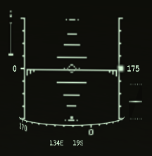
A Heads Up Display (HUD) is shown when at the helm and the capacitor has power. The HUD shows essential information to minimize the need to look down at the console.
Pitch and roll information are indicated by the ladder at the center of the HUD. In the example above, the spacecraft is rolled to the right about 45 degrees with respect to the planet. The nose is pitched down a lot.
Current speed in meters per second is shown at the left side of the HUD. When moving laterally, a lateral speed will be displayed below the speed value. Lateral speed always shows a sign, negative when moving left and positive when moving right. The example shows a speed of 0 and no lateral movement.
To above the speed indicator is the safe speed indicator. Your speed is shown as a horizontal line in the range which raises as you approach the maximum safe speed. Once you go faster than the safe maximum speed (top horizontal bar) your vessel takes damage, with the damage increasing with speed until the vessel ultimately is destroyed.
Altitude in meters is shown at the right side of the HUD. When moving vertically, a vertical speed will be displayed below the altimeter value. Vertical speed always shows a sign, negative when moving down and positive when moving up. The example shows an altitude of 175 meters and no vertical movement.
Next to the square next to the altitude meters indicates that the maneuver drive is in the Hold state.
A heading tape appears horizontally at the bottom of the HUD. The example shows a heading of northwest at about 337 degrees.
The longitude and latitude position of the spacecraft is displayed below the heading tape. The examples shows a location of 134 degrees east longitude by 19 degrees south latitude.
The throttle setting is shown as a graph below the altimeter at the bottom right of the HUD.
The Estimated Time Enroute (ETE) to the next waypoint is displayed at the top of the HUD when a waypoint is set. Waypoints are set using the navigator station.


